How Does A Remote Control Circuit Work Wiring Diagram
By following the instructions in this tutorial you will be able to use virtually any IR remote (like the one from your TV) to control things connected to the Arduino. In the code examples below, we will be using the IRremote Arduino library . This library is fairly easy to use and supports many different IR communication protocols.
Remote Control Circuit Diagram EdrawMax Template
IR Transmitter and IR Receiver are commonly used to control electronic devices wirelessly, mainly through a remote. TV remotes and AC remotes are the best example of IR transmitters. TV generally consists of TSOP1738 as the IR receiver, which senses modulated IR pulses and convert them into electrical signal.
Remote Control Circuit Through RF Without Microcontroller The Circuit
A remote control circuit is an electronic circuit that allows you to wirelessly control various devices, such as televisions, DVD players, and air conditioners, from a distance. It consists of different components that work together to transmit and receive signals between the remote control and the device being controlled.
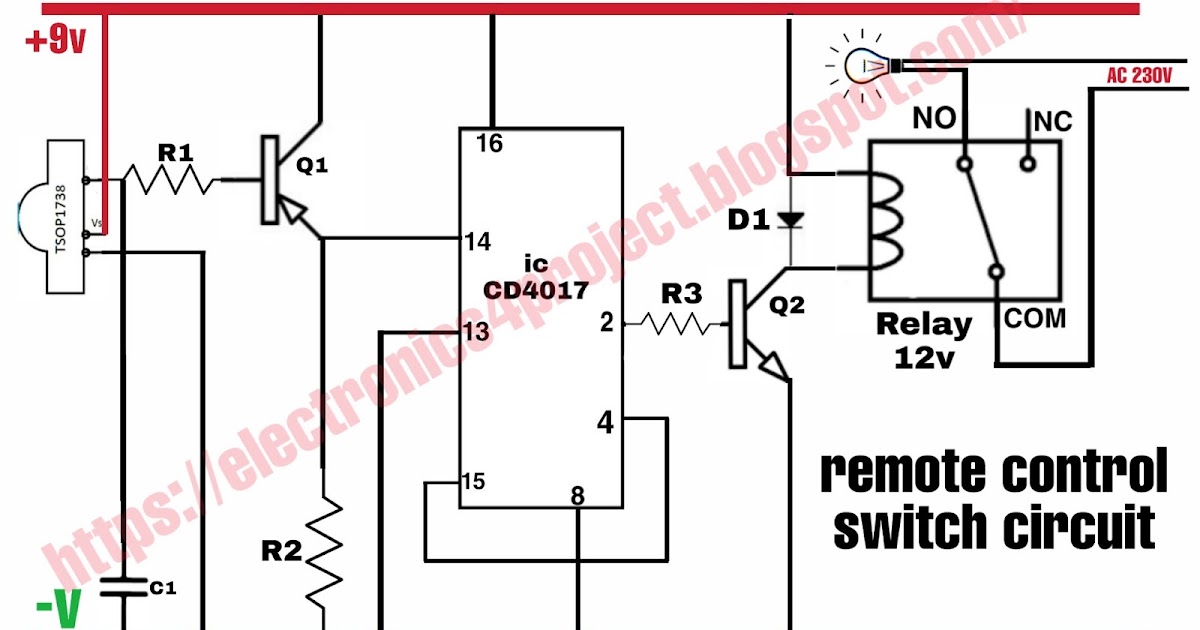
remote control switch circuit diagram
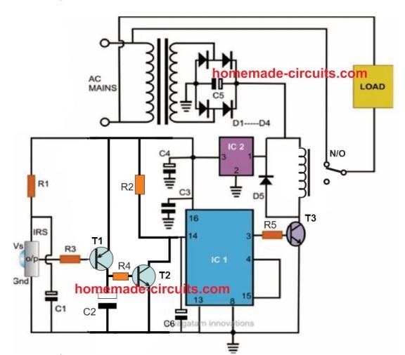
A remote control system for appliances makes our life smarter and easier. The wireless remote control circuit may be based on IR waves or RF waves, IR being cheaper. An IR emitter circuit is based on TSOP at the receiver section. Each TSOP operates at a particular frequency which depends on a number present on it.
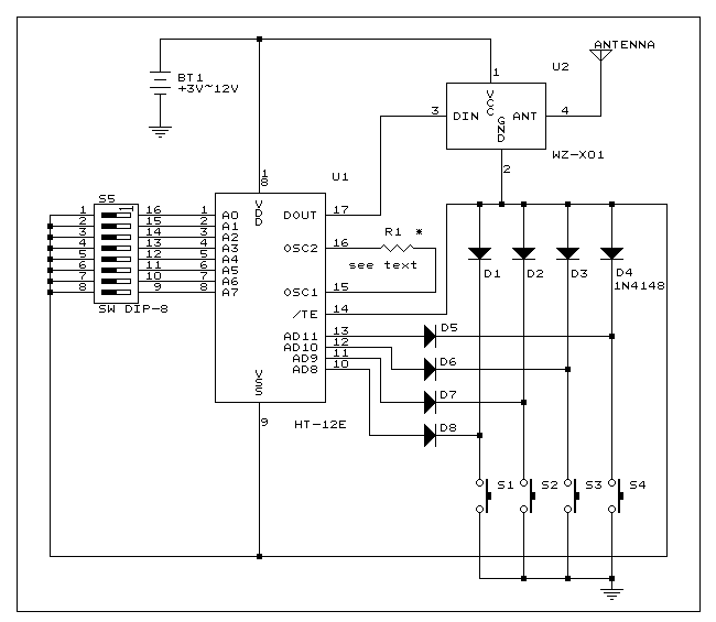
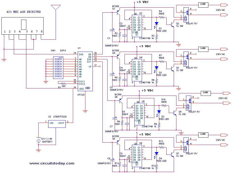
Four channel RF remote control
In this section, I will discuss how to debug the remote control circuit. First of all, don't be angry, and just keep calm! For debugging, we will split the circuit into different sections. L293D IC. Place the IC on a breadboard. Give VCC(5V) and Gnd to the IC and then give the 12V to pin 8. Connect the enable pins of the motors to 5V.
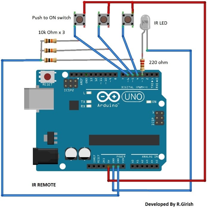
Arduino IR Remote Control Circuit Homemade Circuit Projects
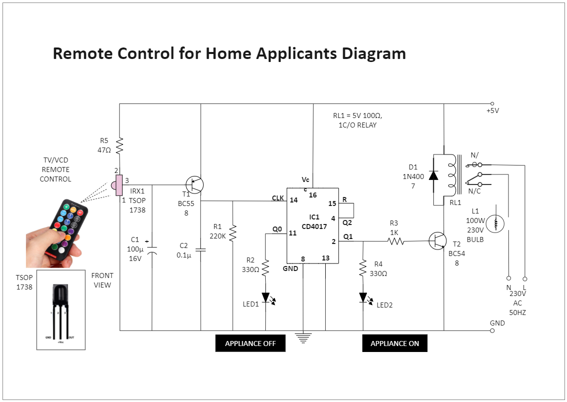
Remote controlled switch circuit November 9, 2018 In this project, let's build a simple Remote controlled switch for appliance controlling. If you know basic concepts of electronics, this circuit is pretty easy to build and test. The core of this circuit are two IC's - which are infra red sensor IC's - TSOP 1738.
How to make remote control on/off switch
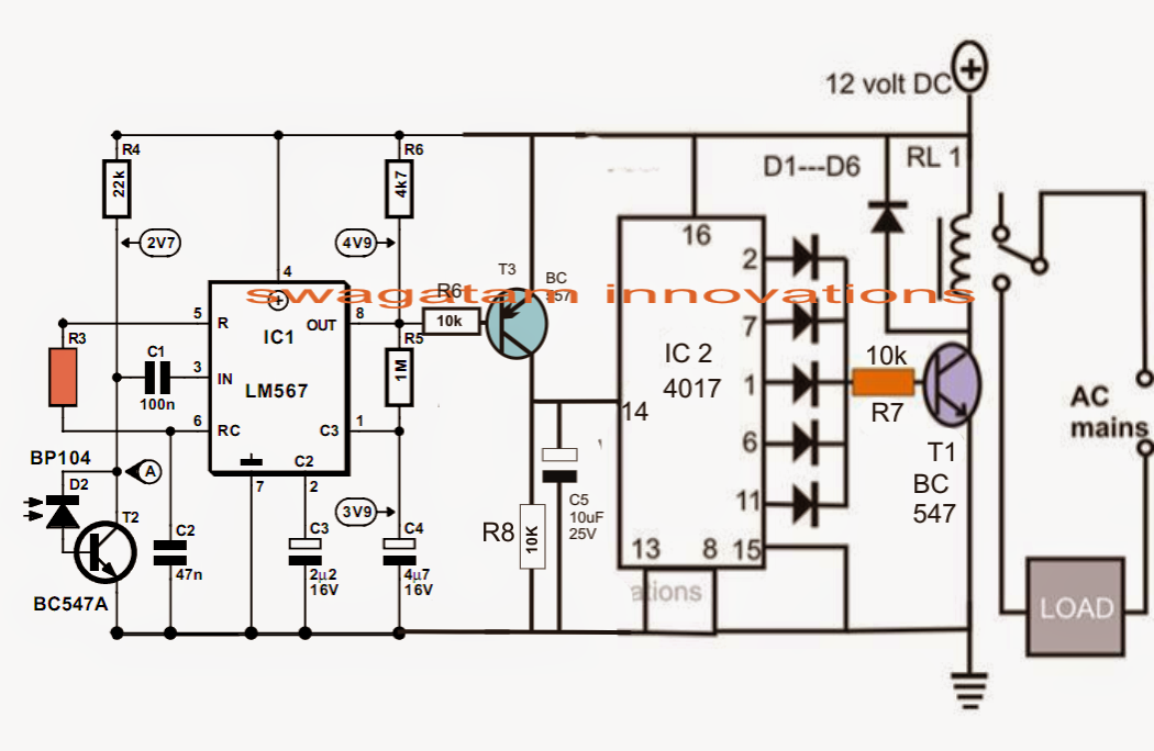
The proposed infrared or IR remote control circuit can be used to operate an appliance ON/OFF through any standard TV remote control handset. In this write up we discuss a couple of these simple infrared remote control circuits designed for controlling any given electrical appliance through an ordinary or TV remote control unit. Introduction
Simple RF Remote Control Circuit without Microcontroller ( No need code)
Step 3: IR Remote. (InfraRed remote control) A handheld, wireless device used to operate audio, video and other electronic equipment within a room using light signals in the infrared (IR) range. Infrared light requires line of sight to its destination. Low-end remotes use only one transmitter at the end of the unit and have to be aimed directly.

Manual button high power DC motor wireless remote controller Remote Control Everything
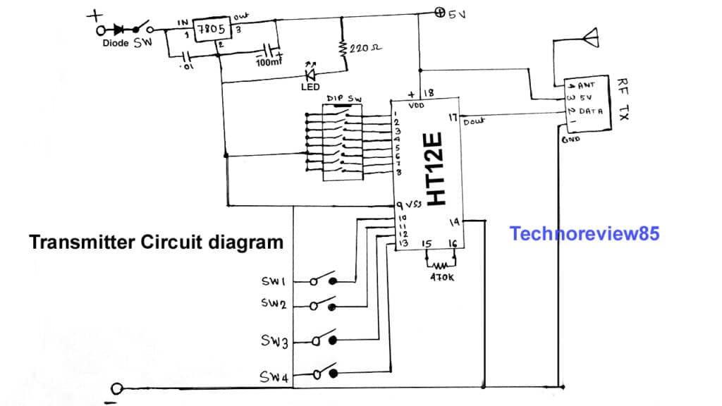
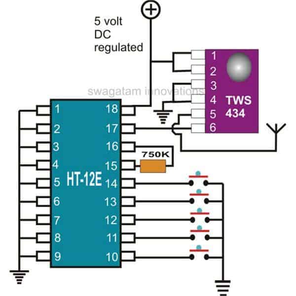
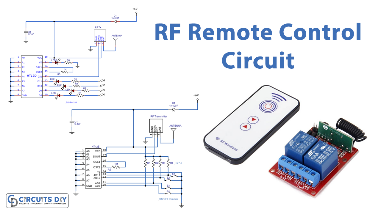
RF Remote Control Circuit Principle When we press any key in the remote, the transmitter section generates the corresponding RF signal and this signal is received by the receiver section, hence it switches the corresponding appliance. A four channel encoder/decoder pair is used in this system.
Remote Control Circuit for Multiple Appliances Circuit Diagram Centre
What are Remote Control Circuits? A remote control PCB as the name suggests, can operate the device remotely, even from a distance. It has wireless connections. But some may also contain wired connections. These remote-control PCBs can be used in LEDs, LCDs, TVs, DVD players, and various types of toys.
arduino uno What's the best way to operate a remote control circuit board? Arduino Stack
Rule 16-010 specifies that remote control circuits to safety control devices where failure could cause a fire or a life hazard, are to be considered and installed as Class 1 circuits. Rule 16-012 deals with circuits in communication cables: • Class I circuit cannot be run in the same cable as communication circuits
FM Remote Control Circuit Using a FM Radio
Next we start the IR receiver by calling the IRrecv member function enableIRIn () (line 10). The irrecv.blink13 (true) function on line 11 will blink the Arduino's on board LED every time the receiver gets a signal from the remote control, which is useful for debugging.
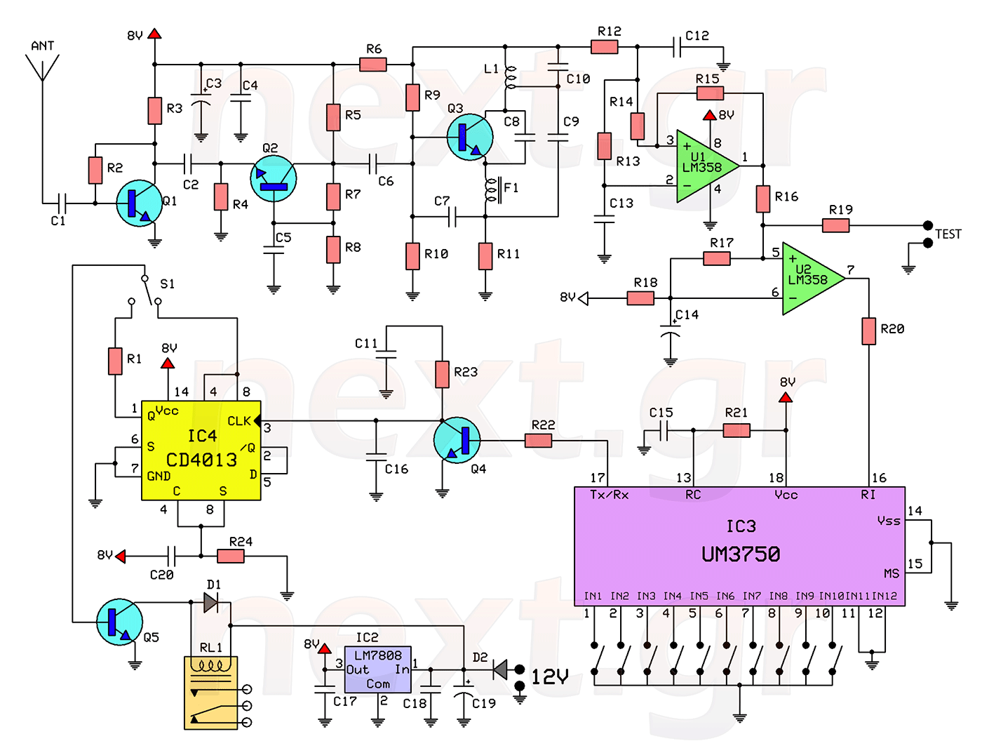
RF Remote Control Circuit using 433MHz and 315MHZ RF Modules
Everything was controlled through electronic circuits in the blue box marked 21. Radio control. Infrared remotes can operate TVs and videos only over quite short distances. The infrared LED is quite small and low-powered and the receiver on the TV or video is small too.. Nikola Tesla, inventor of remote control, 1898. So radio control, which.
RF remote control using Arduino and 433mhz ASK module
Making a 433 MHz, 315 MHz RF Remote Control with Relay Flip Flop. Building a hi-end remote control device using very few components today looks pretty plausible. The proposed remote control light switch circuit idea provides you with the opportunity of building and owning this amazing device through simple instructions.
remote control circuit Automation Circuits Next.gr
Step 1: Where to Procure Components After much research, i have found the following to be reliable, have a reasonable price, and have good selection: - Hobbyking: A Chinese-based distributor with a huge selection of motors, controllers, and everything else. mostly flying things. Shipping takes forever.
RF Remote Control Circuit
TV remote jammer. August 27, 2009. Description. Here is the circuit diagram of simple but highly effective TV remote jammer circuit. Most of the TV remotes have 38KHz operating frequency. A flood of IR…. Read More. In Remote Circuits.
