Wireless Cellphone Charger Circuit
In this project, we will explain about the circuit which is used to charge your phone devices safely by converting 220 volts of AC supply into voltage supply rating of your cell phone. Today cell phone chargers come with different power supply in the market.
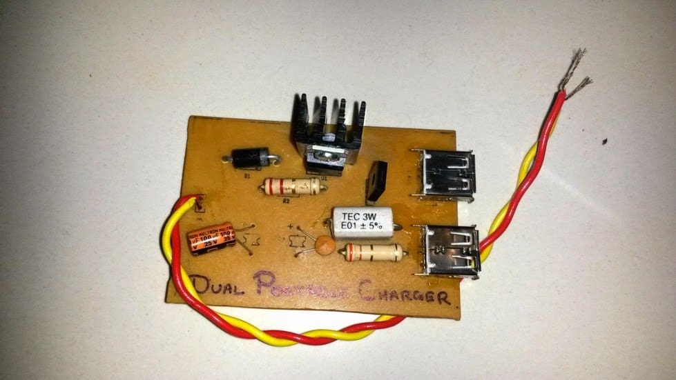
6 Useful DC Cell phone Charger Circuits Explained Homemade Circuit Projects
How it works. Nowadays, the cell phone charger converts AC mains to 5V stable voltage for charging the cell phone (built-in the cell phone there is already a charging system and Battery Management System). Small & cheap mobile charger. Inside the cell or mobile phone charger is just a 5V switching power supply.
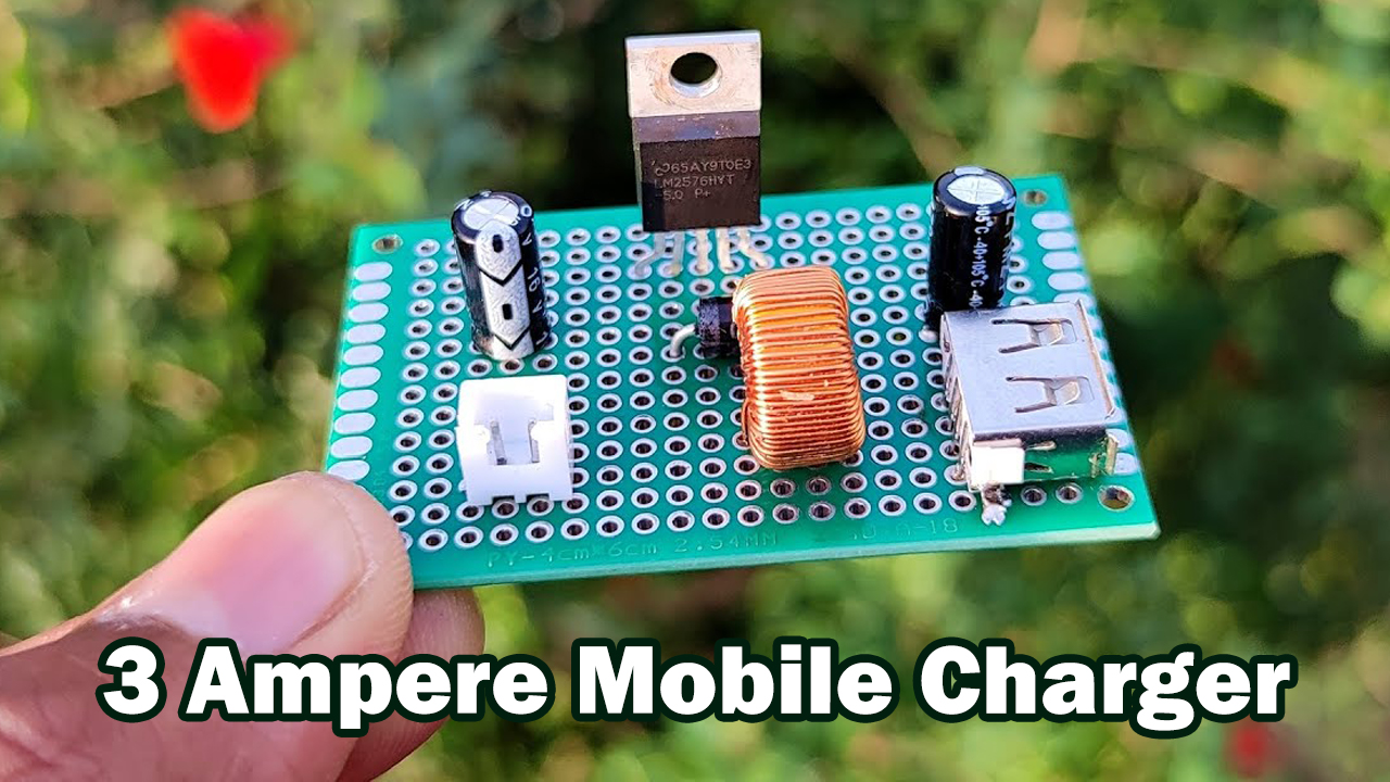
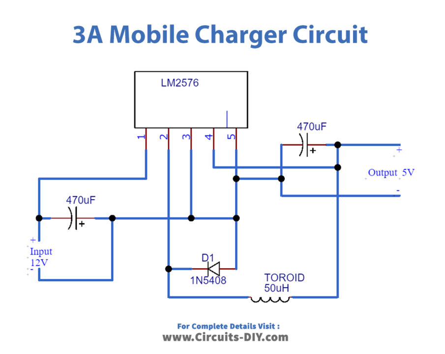
3 Ampere Mobile Charger Circuit using LM2576
How the SMPS Circuit Works The circuit can be understood as follows: The mains input which could be anywhere between 100 and 280V is half wave rectified and filtered through shown 1N4007 diode and 10uF/400V input rectifier stage.
Cell Phone Charger Circuit Diagram
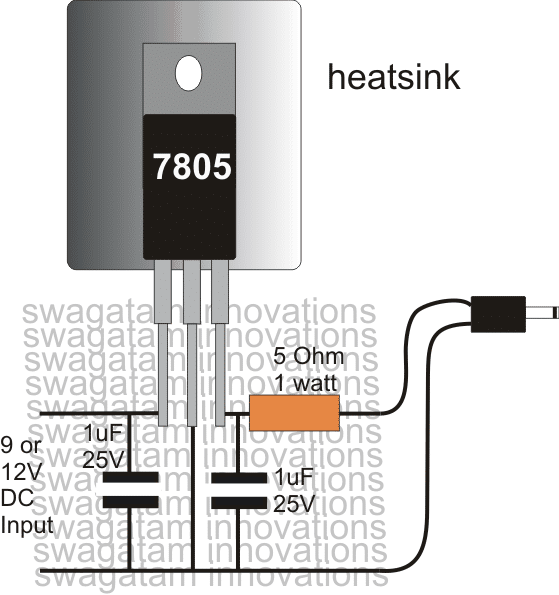
Working Explanation Most of the mobile phones generally charge with 5v regulated DC supply, so basically we are going to build a circuit for 5v regulated DC supply from 220V AC. We will use a step-down transformer to convert 220V AC to 9 V AC. The voltage rating of the transformer should always be more than the required output voltage.
6 Useful DC Cell phone Charger Circuits Explained Homemade Circuit Projects
A DC cell phone or mobile phone charger is a device which charges a cellphone from an available DC supply source. The device converts the unregulated DC source into a constant current and constant voltage output which becomes safe for any mobile phone charging.
Wireless Mobile Phone Charger Circuit Diagram Pdf Wiring View and Schematics Diagram
To recharge a mobile phone, a 5-volt DC power source is required, with a charging current of 700 milliamps. However, the actual current needed depends on the charging duration. For rapid charging within a short period, a higher current exceeding 700 milliamps is necessary. Conversely, for extended charging periods, such as 10 hours, a lower.

Circuits Room Mobile Phone Charger Circuit Diagram
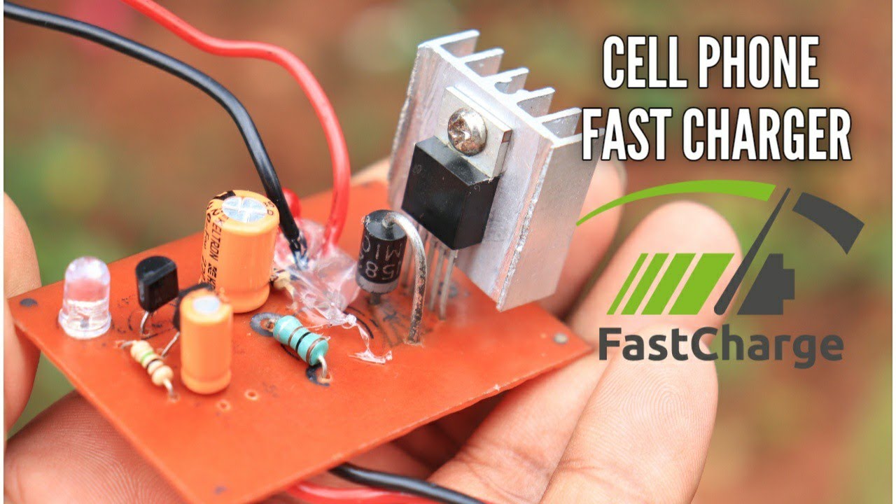
Cell phone charger - DIY fast mobile charger circuit and free PCB layout. This portable mobile charger is based on the IC LM2576 voltage regulator IC. You.
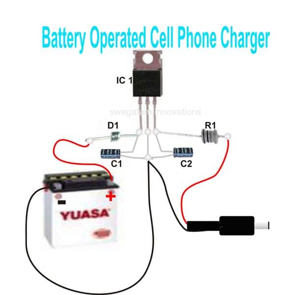
ELECTRONIC CIRCUITS ASSEMBLY 4 to 5 Cell Phone Charger Circuit
A mobile battery charger circuit is a device that can automatically recharge a mobile phone's battery when the power in it gets low. Nowadays mobile phones have become an integral part of everyone's life and hence require frequent charging of battery owing to longer duration usage.
Circuit Diagram Of Mobile Charger Nokia
Mobile phones generally charge with 5v regulated DC supply, so basically we are going to build a 5v regulated DC supply from 220 AC. This DC supply can be used to charge mobiles as well as the power source for digital circuits, breadboard circuits, ICs, microcontrollers etc.
3 Ampere Mobile Charger Circuit using LM2576
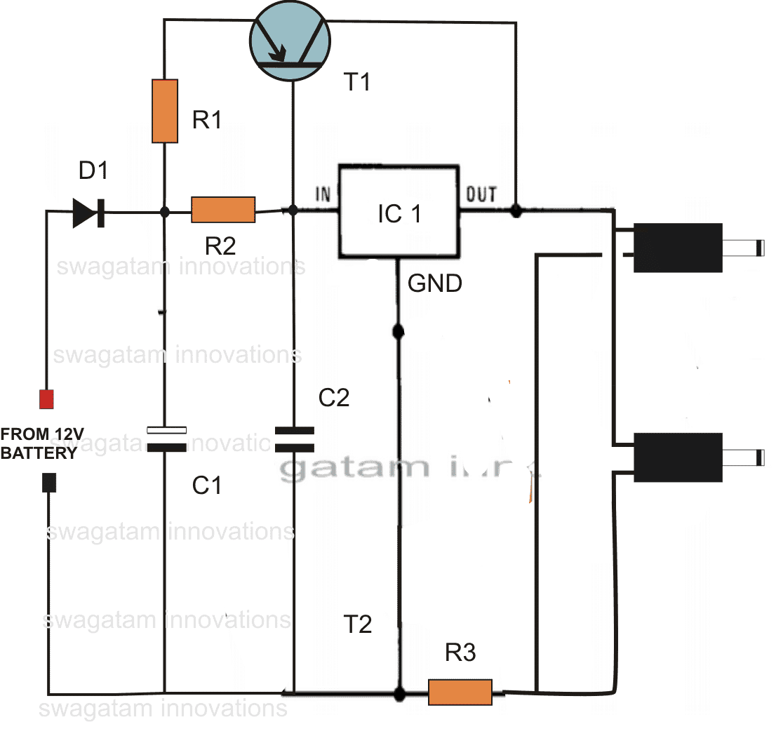
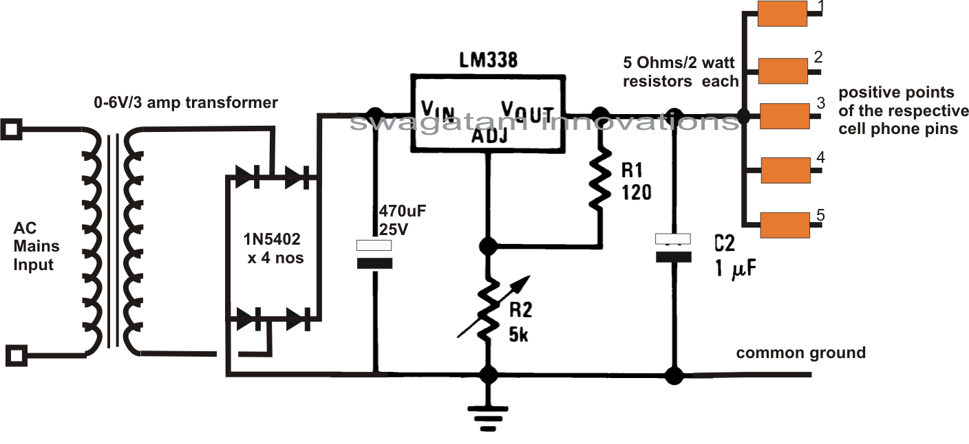
Schematic of Cell Phone Charger Circuit. Most of the Mobile phone batteries are rated at 3.6 V/500 mA. A single pen torch cell can provide 1.5 volts and 1.5 Amps current. So if four pen cells are connected serially, it will form a battery pack with 6 volt and 1.5 Amps current. When power is applied to the circuit through S1, transistor T1.
6 Useful DC Cell phone Charger Circuits Explained Homemade Circuit Projects
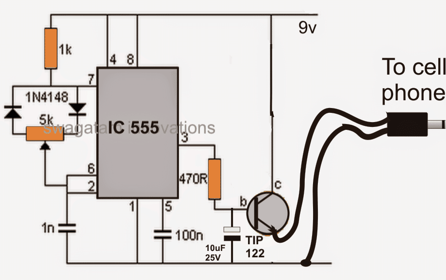
Portable Cellphone Battery Charger Circuit Diagram. D2 = 3mm. Red LED. Timer IC NE555 is used to charge and monitor the voltage level in the battery. Control voltage pin 5 of IC1 is provided with a reference voltage of 5.6V by zener diode D1. Threshold pin 6 is supplied with a voltage set by P1 and trigger pin 2 is supplied with a voltage set.
6 Useful DC Cell phone Charger Circuits Explained Homemade Circuit Projects
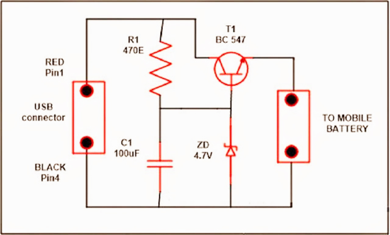
This simple usb cellphone charger circuit can give regulated 4.7 volts for charging the mobile phone. USB outlet can give 5 volts DC and 100 mA current which is sufficient for the slow charging of mobile phones. USB Cell Phone Charger Circuit Schematic Most of the Mobile Phone battery is rated 3.6 volts at 1000 to 1300 mAh.
Mobile Phone Travel Charger Circuit Diagram
Knowing how to wire up a mobile phone charger is essential if you want to be able to repair any problems that may occur. As the name implies, a cellular phone charger wiring diagram gives a detailed description of all the electrical components required to power up your device.. 6 Useful Dc Cell Phone Charger Circuits Explained Homemade.
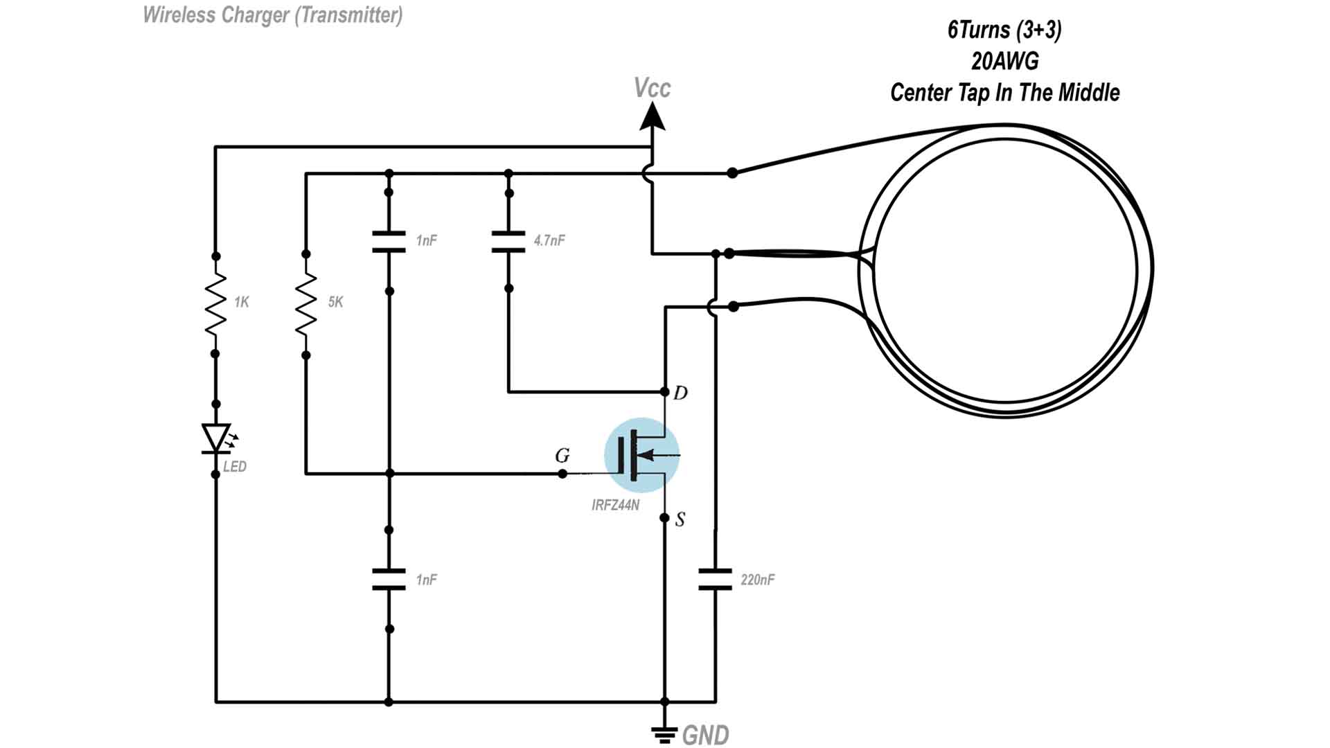
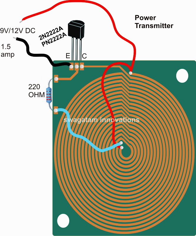
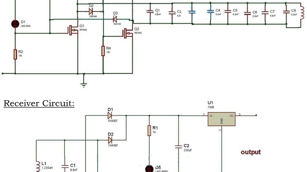
Homemade wireless smartphone 5V charger DIY circuit
Bonnes affaires sur les galaxy mobile dans téléphonie et pda sur Amazon. Large sélection de produits high-tech. Livraison gratuite (voir cond).

How to Build a Simple PWM Controlled DC to DC Cell Phone Charger Circuit Science Fair Project
November 5, 2017 29603 - Advertisement - Mobile phone charger available in the market are quite expensive. The circuit presented here comes as a low cost alternative to charge mobile telephones/battery packs with a rating of 7.2 volts, such as Nokia 6110/6150. Mobile phone charger circuit Mobile charger circuit
6 Useful DC Cell phone Charger Circuits Explained Homemade Circuit Projects
The article presents a simple yet extremely efficient smartphone charger circuit using a boost converter circuit. Let's learn the details.